Monday 5 December 2016

Build Your Own GT40 Replica Super Car

Introduction

Sick of Ferrari dominating the sports racing scene and upset at the rejection by Enzo Ferrari of a deal to acquire Ferrari, Henry Ford decided to go all out and build a car to beat Ferrari at the Le Mans 24 hours. The result was the legendary Ford GT40.


Original GT40 cars are extremely rare and valuable. Prices start around $6,000,000, the 1966 Le Mans winning car is worth in excess of $20,000,000. No fear, building a very accurate replica is very achievable for most people with reasonable hands on ability.

As kit cars go, the GT40 is one of the only cars you can build that's also a good investment. Typically you'll spend around £22,000 - £30,000 building it, and resale prices are £50,000+ and even 25+ year old examples requiring work will sell for £35,000+.

GT Forte was established to help make building a GT40 more accessible for anyone who wanted to build a decent replica without having to have budgets in excess of the average person.

Original I considered using cheap donor parts like the Rover V8 engine, but, on further research I realised these were no cheaper to buy and rebuild than a genuine Ford 302 small block motor, and yet the resale value of the car is considerably more with the Ford V8. For example certain old GT40 replicas were £15,000 more with a Ford than a Rover, and yet the build cost difference is negligible.

So after discussing with many GT40 builders what issues they had an what features of the original cars were important to them, I designed the GTs40 replica kit we offer for sale today.

How do you start building your own?

There are several options on how to start the project. The car has been designed to make it accessible and to allow people to make as much or little of a project as they feel comfortable with.


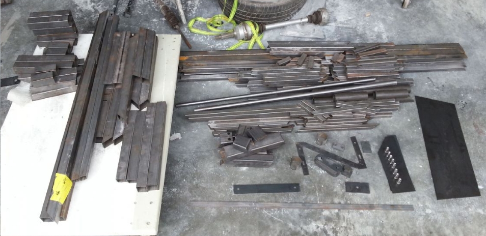
We offer the chassis as a flat packed laser cut tube kit. This is currently proving very popular. Essentially it's like a giant puzzle, the tubes are all accurately cut on a special laser cutting machine with an accuracy of +/- 0.1mm and each tube has locating features similar to puzzle pieces so that they slot together with neighbouring tubes. The tubes require tack welding to hold them in place, and then fully welding when the complete chassis structure is all together. We've sold around 25 such kits, and to all types of people with a range of experiences with welding. Even first time welders are succeeding in doing a good job of constructing the chassis.


Starting at this point not only allows you to start for a low initial outlay, it also makes more of the project, you really are constructing the car yourself. For those with a modest budget you can buy parts each month to suit your pocket and keep the project rolling on. The only really big 1 off outlay would be the bodywork, but that can come towards the end of the project if need be.

Another popular way to start the build, is to buy our deluxe starter kit. This kit is essentially everything you need to build a rolling chassis with a body on. You will need the donor car parts or to buy the bespoke new replacement donor parts that we offer. In this kit the chassis is already welded together and powder coated, so you are starting the assembly straight away.

The laser cut flat packed chassis is £950 and the deluxe starter kit as described above is £8,000. www.gtforte.co.uk

What do you need to build a GT40?

You'll need somewhere to build it obviously, but, a lot of builders make do with a single garage, a larger workspace if possible is ideal if you happen to have it. You'll need tools, but, a typical DIY tool set of spanner, screw drivers, pliers and sockets etc will cover most of what you'll need. When cladding the chassis in aluminium sheet you'll need a riveter, a pneumatic one ideally as your hands will soon hurt if using a traditional hand riveter. However items like this can easily be borrowed or hired when needed.

In terms of skills, you'll learn most of what you need as you go along. The great thing with any kit car is there are plenty or skilled and knowledgeable people around to give you advice and lend a hand. If you put up shelves at home, do DIY or service your own car you'll find the project is within your ability.

We have an active Facebook page, Drivetribe account and there's a massive GT40s forum and owners club with regional meets that you can visit and get help and advice from. All our customers get access to a shared online Dropbox folder, where you'll find the build manual and I post useful documents and drawings in response to customer questions. Customers are encouraged to do the same with things they find out, and do to their cars in order to help others in the community of builders.

www.gtforte.co.uk
www.facebook.com/gtforte
Drivetribe - GT40 Builders - www.drivetribe.com
Twitter - @gt_forte - www.twitter.com


Saturday 23 May 2015

BTCC Engineering

Since 2013 the British Touring Car Championship has run to the NGTC rules. The next generation touring car concept was introduced to control the costs of competing in this form of racing that had hit multi million pound budgets under the previous S2000 rules.

The BTCC has long been one of the world's most exciting and competitive championships and has attracted manufacturers and top drivers from around the globe. It has a massive following and aside from F1, it draws the biggest crowds both at the circuit and on TV.

NGTC basically defines a lot of the running gear of the car to a kit of standardised components. Only the bodyshell, engine  and the body styling kit can change between cars/teams. The engines are turbo charged 2 litre 4 cylinder  types with equivalency rules to ensure parity of performance.

So the room for engineers to find performance is severely restricted. However because the competition is so close (often only tenths of a second covering most of the grid) small detailed improvements can make big differences to grid position.

BTCC teams range from very professional manufacturer teams to very enthusiastic amateurs with a ton of volunteer help. When you are doing any serious race car engineering work it's very important to know what you are working from.  Touring cars tend to be hand built and parts made up ad hoc as the cars come together so knowing exactly what you have can be a problem.  In F1 for example every single part will be CAD modelled allowing you a lot of possibilities for analysis and simulation.

So I think it's really important to try and understand what you have and so part of that is to build CAD models where possible in the case of my current project I've assembled CAD models of all of the standard kit components to begin with. The team have a limited budget but also practical requirements for spare parts and the desire to try and keep up with developments.

The flat floor at the front creates an aerodynamic splitter element and is one area that can be changed by the teams as it must fit an offset of the front bumper/air dam plan view silhouette. As with all race cars you are looking to reduce the weight and keep it as low as possible. This team needed spare floors and at the same time we've reduced the overall weight and made the floor area larger to the extent allowed by the regulations.  As the front air dam creates a high pressure area in the front of the car and on top of the splitter with a reduced pressure underneath you end up generating down force.  As down force comes from the pressure difference between top and bottom of the splitter multiplied by the area of the fool that that pressure acts upon, the larger the area of the flat floor the better. In this case we've added about 1300 cms Sq so hopefully that and 3kgs less weight will make for very cost effective performance improvement.

The other part of this first stage of upgrades is to redesign the body kit to further reduce weight and decrease drag and increase down force.  We don't have the budget currently to conduct wind tunnel development and whilst we have CFD capability without the budget to scan the cars shape and create CAD data for this we can't make much use of it. So we are using experience and common sense to try and make improvements in the area.

As the car is currently 3 kgs over weight and front weight balanced we are aiming to reduce the weight of the front bumper, wings etc and then if required to make up the minimum weight with ballast low down in the rear of the car. As the cars race performance is dependent on how they use and abuse the tyres, balancing the front to rear weight split to equalise tyre use is likely to be important for overall race performance.

Thursday 5 March 2015

How Autosport GP Engineering bring dinosaurs to life.

How do you take a design brief to create a realistic 3D Jurassic Park Velociraptor and produce a pair of 1m tall figures in just 4 weeks including Christmas?

Well the answer is a lot of hard work, skill and a not inconsiderable amount of advanced technology.

Equinox Products of Whitstable regularly produce fibreglass figures for Harry Levy Amusements of Broadstairs. They came to us in early December with a sketch of a new machine they had to have displayed at a games and amusements exhibition  in the 2nd week of January. Under normal circumstances you might expect this to be a 4 month project not a 4 week one, especially as across Christmas all suppliers are closed.

Normally with these projects someone will produce a 3D CAD model of the end figure, or a skilled artist might hand carve it. In order to make a realistic looking dinosaur a particularly skilled sculptor would be required and they would need plenty of time, both of which are in short supply. In order to create from scratch a 3D CAD model with such detail is a very time consuming project and requires extremely experienced CAD surfacing designers.

Once a CAD model has been produced patterns in dense foam are produced. These patterns, are essentially the finished items only split into sections so moulds can be made from them. 3 axis CNC machining centres that are computer programmed by extracting the geometry directly from the 3D CAD model, are used to produce the patterns.

Moulds are then produced in such away as they can be split apart to extract the fibreglass finished figures once they are laid up inside. In each of these processes you can see there is a lot of time spent producing items that are just links in the chain towards being able to produce a final figure, and then a production quantity of them, in this case 62 items across the first few months of 2015.

Four weeks including Christmas, made this traditional approach a total non-starter. So a new approach had to be taken. We sent out for a model toy dinosaur figure and it was optically scanned. Optical scanning is an extremely accurate (0.02mm resolution or higher) method of capturing 3D geometry. It's used for reverse engineering and for inspection because it can capture, for analysis, forms that are hard to capture by other methods.

The resulting data from the scan is in the form of a mesh of data points representing the form of the dinosaur toy. Unfortunately the original pose of the toy was not suitable for how it was required to fit on the finished machine. We used a combination of advanced software, similar to that used to produce CGI movies, to re-pose the figure, and then cover the mesh with CAD compatible surfaces that can then be used for manufacture. Some mechanical fixing elements were added in the 3D CAD model at this stage.

Finally using this CAD data we 3D printed in plastic the finished dinosaur. However being over 1 m tall our 3D printers couldn't print it in 1 piece, but, luckily the software allows us to split it into smaller parts and add socket and pin details so that it can be clipped and glue back together after.

Three were made in total two for the exhibition and a third was used to make the GRP moulds from so that a production run of 62 figures can be produced. We were thinking of creating a bit of a stir in the local press by burying some spare parts in the beach at Whitstable and seeing what the reaction was when the were uncovered!

Can we help you with a similar challenge? If so then please contact me on 01227 392840 or autosportgpengineering@gmail.com


Friday 6 February 2015

How Marussia might be able to get on the grid for 2015

So news has hit today that the hopes of the Marussia F1 team (now Manor) have been dealt a huge blow by the veto from Force India to them using the 2014 car although it doesn't comply with 2015 regulations.

As there is reportedly over £30 million in prize money from last year at stake I can imagine how the teams backers are desperately thinking of ways to get a 2015 compliant car ready asap. I've also been thinking about how you might be able to short cut the process so they can have a car ready in time.

The apparent stumbling block is that the front bulkhead on the monocoque needs to be 50mm lower than in 2014, so you need a new monocoque design. Marussia apparently had a 2015 design complete and pictures are being circulated of a wind tunnel model. So most of the thought process for the nose and monocoque has been done, but, there isn't time to manufacture a new one.

In order to manufacture a new monocoque you first need to machine a pattern out of high density foam or aluminum from the CAD model. This is several days/weeks of machine time. After this you have to make carbon fibre moulds from the pattern, again many days work, and then you get to make an actual monocoque. So you are looking at a vast amount of time and money both of which they don't have.

However there are ways to short cut this process. They are going to have to retain as many parts as possible from the 2014 car, so I would want to choose a point along a 2014 monocoque and cut it off (figuratively) retain everything rearwards of this point, and blend the rear of the 2015 nose design they already have into this point on the 2014 monocoque. What this allows you to do is reuse most of the monocoque pattern from 2014, saving machine time, also you can cut the moulds back to this point, remould a return flange on them and then the majority of the moulds can be reused. You can then machine a small pattern which is the blend from the 2015 nose to 2014 tub, make moulds from this with return flanges that can bolt onto the main section, and away you go, you have a new set of moulds from which a 2015 tub can be made. Reducing cost and time by at least 50%.

Unfortunately for them the external shape of the monocoque is not the only problem to overcome, packaging the steering, pedals, brakes and front suspension into this new space with the minimum of new components will be an equally difficult challenge, but if they are true racers where there's a will there's a way.

It might not be a typical F1 solution, or result in a particularly attractive car, but that's the least of their worries at the moment. I'm sure we'd all like to see them on the grid however they manage it. They clearly have resolve to keep trying even after the apparent death, after all I'm typing this blog one of their PC's that was sold off at the disposal auction.

Darren George
ex-F1 Design Engineer

Monday 24 February 2014

John Barnard Article in Racecar Engineering

This months edition of Racecar Engineering magazine (http://www.racecar-engineering.com/) has an interesting article about the F1 design innovator John Barnard and his career. Growing up in a racing family and with a desire to become an F1 designer, John was a hero of mine, and the one engineer I desperately wanted to work with and learn from. After losing out on just such a job offer whilst he was at Arrows, I eventually did get my dream job working with him at the age of 25 at B3 Technologies, when he was design consultant for Prost.

It's always interesting to read articles about people that you know ever so well. Have you ever read an article about something or someone you know well? Well if you have you'll know that journalists never seem to catch the person of story correctly, and it's disappointing when the rest of the world then takes that as the gospel just because it's laid down in print.

Well so it's true to a certain degree with articles written about John. I must admit that we fell out in the end, but, I think I have enough respect for him as an engineer, and I have enough self-respect and passion for engineering that I can give a fairer assessment of him as a person than any journalist interviewing him can.

What comes across in the interview is his design genius in how he innovated step changes in F1 technology, which is as you can imagine is slightly far fetched. By the mid-late eighties F1 design teams were expanding and consisted of ever larger numbers of engineers, and by the late nineties when I first got involved there were up to 50 people designing parts in each team. So to say that one person was responsible for the whole idea and for making it work is stretching the truth a bit far. It annoys me today the way that Adrian Newey is lauded as the design for Red Bull, he might have ultimate responsibility but he is really a manager of very many talented individuals, the original ideas for many innovations and developments will have come from a number of sources that you will never hear credited.

The paddle gear change for example I was told was already on the drawing board when John joined Ferrari. If this is the case is it really fair to credit him with the idea? In practicality I believe it is actually fair, because, what noone really stresses about John, is that he is very supportive and has incredible attention to detail. I have no doubt that John made that idea work, even if it wasn't actually his initial idea. He was always prepared to listen to your ideas, work through them with you, see how they'd fit into other ideas and concepts and help you detail the design through to manufacture and realisation. So he is exceptionally supportive in that way and as a very young and inexperienced engineer it was so exciting to have that support and encouragement from an icon like him. Working under him was not easy, extremely long hours including Saturdays and no care that you had a life and family outside of the company. That's what F1 is like, it's total immersion, and I bet everyone is grateful for the regulated August break nowadays.

The contradiction is that he would never credit anyone publicly with any ability. I bet if you were to ask him about the current crop of technical bosses that used to work for him, his opening line will certainly be "when I first employed him, he couldn't draw a milk bottle". F1 is not only competitive on track, but, it's a competitive working environment. You don't get your crack at the top jobs unless you are prepared to stab a few friends in the back, and, I guess maybe this side to him is just a reflection of the competitive environment.

It's true that he knows how to explode and scream and shout, during the first Gulf war his employees termed it "Scudding" after the Iraq missiles. Basically if you did something wrong you could expect him to explode like a Scud missile. These explosive episodes were never fun to be on the receiving end of, but, actually in all fairness he didn't hold grudges and saw the mistakes as interesting problems to be worked through. It was sometimes hard not to laugh, one time he was punching himself in the head in the middle of the design office after being given some bad news, the barer of that bad news, a fabricator had to point out he was "a fucking psyco!". A few minutes after a scudding, he'd likely be your friend again and sat on your shoulder enjoying the challenge of finding a solution to the problem. And this is where you see the passion for engineering that he has, and that I guess even in retirement he hasn't lost. By the time I worked with him, he wasn't bothered about going to the track and races, his passion was in the fine details and in making ever more perfect components. The compound benefits of fine detail improvements was his idea of a significant performance advantage. It upsets me to see some of the current crop of F1 cars, in that some components have still not matched the detail we achieved in the late 90's early 2000's on the Prost!

Another side that doesn't come across in interviews and articles is that he's actually very funny, he's totally un-PC and everyone feels sorry for his long suffering wife. He definitely calls a spade a spade in company he feels comfortable with, he's shy in large groups and new environments, and therefore you only see the real side of him when he's comfortable with you. That's a double edged sword, because only those he's comfortable with will get a full assault scudding, but, also those people are the only one's who get to see the best side of him. He tells a really good story too and as you can imagine with the length of his career he has a lot of stories to tell. If ever you needed a break from an intense design session with him, we all developed little tricks to set him off on story time. He is also colour blind and to keep ourselves amused we'd like to tell him the wrong colour for each line on the CAD screen, so when he next referred to it we could try and confuse him.

At the launch of the Prost AP03 John and I flew out together and the plane had to land at a different airport due to bad fog. Whilst waiting for several hours on the runway to make the short flight back to Barcelona he told me how the deal unfolded with Enzo Ferrari the first time he set up a design office for them. He wouldn't divulge numbers but did say that he was asked how much it would take to get him on board, so he wrote on a piece of paper a number he thought so outrageous Ferrari wouldn't pay it, only for Enzo to agree instantly. That trip we got to our hotel at about 4am and we had to leave for the circuit at 6am, I was up and ready in reception with all the French mechanics who distrusted John and anyone associated with him, and there was no sign of John. I had the reception call him only for him to still be in bed and decide we could stay in bed for another hour or so!

At that test the pit lane was full of gossip mostly spread by Alex Wurtz who was riding up and down pulling tricks on a mountain bike, about one teams technical director who had just been forced to resign over allegations he had a foot fetish. Apparently this guy been fondling the feet of several of the teams female employees under the guise of a secret project. John found it hysterical and joined in the conversation in his normal no nonsense manner.

I think in conclusion it's a shame he wasn't more of a racer, and if he'd committed more to being a traditional technical director and taken full control of the cars performance and stuck with teams and seen through all the developments to their conclusion you'd see a CV with more championships than Adrian Newey. But, John is a real engineers engineer, and it's a shame that the general F1 public can't get a better look at the details of the components and designs he directed. So for young aspiring engineers, try to see through the media's obsession with pinning all the work on one person and forget about the wild fanciful innovations that are going to revolutionise performance and concentrate and learn to love the details, take concepts and push them to the limit by looking at the fine details. Radical innovations may come as a result of your detailed understanding of the problem, but, also you'll only ever get the best out of any idea if you don't focus on the detail. To all young engineers who aren't going to get the benefit of learning from John now, but, hopefully you can find someone like him who is prepared to show you enough respect to nurture and guide you to be a better engineer.

Sunday 29 December 2013

Active Brake Balance Control in F1

Some time ago I designed an active brake balance control system for the Prost F1 car, from memory it was for AP04. The idea was that aerodynamic load builds up differently front to rear with respect to speed and therefore when a driver brakes into a corner and slows the car the load on the tyres and therefore the amount of grip front to rear changes as the car slows. The front wing is far more efficient than the rear, and so as the car slows the brake balance should shift progressively to the front.

Also what we found is that the difference in brake hose length between the front and rear mean't that the rear brakes take fractionally longer to come up to pressure on rapid application of the brake pedal, than the fronts do. So very briefly you have a lot more front bias than you would ideally want.

So our answer was to develop an active brake balance control system. It's hard to know what the other teams were doing at the time, but, we were pretty confident that we were the only ones using it. It never actually got raced because the rules were changed to ban it as soon as we were ready to race it. It seems that 2014's regulation might require this kind of system and that the rules may have been changed to allow it once more.

The heart of any active system is the Moog valve. This is a servo hydraulic control valve that F1 cars use to control the throttles, gear change, and in the early 90's active suspension systems. It's a very sensitive and rapidly responding valve with a built in feedback system that allows you to control the pressure in a system very accurately, and extremely quickly.


The active brake balance system was in essence very simple. All we had to do we 'T' off of the rear brake hose and put in a hydraulic piston. On one side of the piston was the brake fluid and on the other side was the hydraulic fluid controlled by the Moog valve. The hydraulic fluid circuit also included an accumulator and obviously a high pressure pump (the same pump is used for the gear change and throttles). The Moog valve was controlled by software that had the cars speed, front brake pressure and rear brake pressure as inputs. The software did the calculations to compare the front to rear brake pressure split to the nominal selected balance with respect to speed, so in essence we had a 2D map of what brake balance we wanted for each particular speed. The Moog valve then regulated the pressure of the rear brake line increasing or lowering the pressure many thousands of times a second to maintain the optimum balance.

For 2014 with the addition of extra KERS harvesting and therefore variation in the amount of braking that the rear of the car sees during this harvest, this active balance system would be able to reduce rear brake line pressure during harvesting to keep the balance stable.

The simplicity of this system mean't that if there was a failure in the active system the rear brakes would still function as normal because the separator piston had limited travel and if the hydraulic pressure were to fail then the piston would move back against a hard stop allowing the brake master cylinder to build pressure as in a normal system.

Sunday 15 December 2013

F1 cost capping

There's been a lot said recently about the proposal to apply budget restrictions in F1 because a lot of teams can't afford to compete anymore.

I think that's been part of F1 since it's inception and the highly competitive nature of sport will always drive costs up but there must be a limit to how much sponsors will put in before it's no longer cost effective.

From the inside as an engineer the scale of spending is even more apparent and shocking than the spectacle you see each weekend. For example at Prost we spent £15, 000 making two ratchet tools to remove the nose box. Why? Because we could it's as simple as that.  The tools were beautifully designed and made and no consideration to cost was ever given to it. Now that was in a back of grid team that went bust 6 months later,  so imagine the attitude that a top team would be taking.

I don't want to see a slow down in development ir a reduction in staff obviously because that would hurt people like me. I'd like to see a reduction in waste and therefore the cost in that. We made some carbon rear wishbones for Jaguar. 5 sets to a new design proven to be better in the wind tunnel.  They had to be done in a rush to get to the Australian GP. The day we finished them they updated the design because further wind tunnel testing had proven another design change was even better. So all 5 sets were scrapped and we started again to the new design. 

The process for making a carbon wishbone calls for lots of tooling specific to each design. You have to make aluminum patterns,  carbon moulds off if these patterns,  then wishone halves out of these moulds and then bond them and final machine them. The aluminum for the patterns is already many thousands of pounds and machining time is 90 per hour or more and they take days to machine. The waste of 5 sets of wishbones like this is possibly close on £100, 000 today.  And it's pure waste which is just accepted.

So my cost capping rules would first look at finding ways to ensure parts are homologated in such away as to prevent design and manufacture of endless new parts that subsequently don't get used.